


Virginia Diodes Inc.
製品のお問い合わせ
ベクトルネットワークアナライザー拡張モジュール(VNAX)
- カテゴリー
-
- RF、ミリ波、テラヘルツ
- ベクトルネットワークアナライザー拡張モジュール(VNAX)
Virginia Diodes Inc.
概要
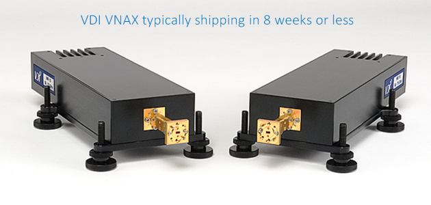
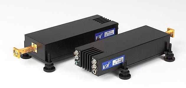
Virginia Diodes Inc社のVNA拡張は、高性能ネットワークアナライザーの周波数をTHz帯域まで拡張します。
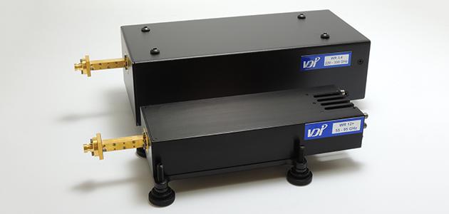
26GHz~1,100GHzまでのモデルがあり、さらに他の帯域も開発中です。
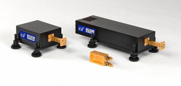
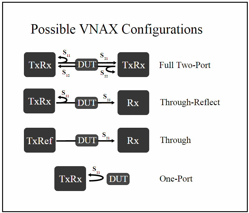
Virginia Diodes Inc社は、フル機能のトランシーバー(TxRx)モジュールに加え、特定のアプリケーション向けに最適化されたパフォーマンスを提供する送信基準(TxRef)モジュールと受信専用(Rx)モジュールも提供しています。
これらのモジュールは、高いテストポート電力と優れたダイナミックレンジを組み合わせることで、業界をリードするパフォーマンスを実現します。
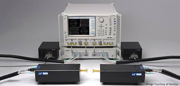
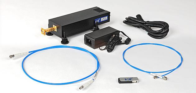
ほとんどのネットワークアナライザーと互換性があり、プローブステーションやアンテナチャンバーに統合できます。また、Virginia Diodes Inc社の PM5パワーメータと併用することで、パワーレベリングとスイープもサポートされます。
オプション
- テストポート出力の向上(一部の周波数帯域のみ)
- マイクロメータ駆動可変アッテネーター(約0~30dB)
- 1.2m~5mのケーブル構成(標準構成は1.2m、5mオプション)
- 導波管校正キット
- 高損失環境向け拡張ダイナミックレンジモジュール
一般仕様
| VNA Extension Modules WM-250(WR-1.0) to WR-28 Mini |
|||
|---|---|---|---|
| Description | Specification | Connector | |
| RF Input | Typical / Damage, -20 Option(Default) | 10dBm ± 3dB / 16dBm <20GHz | 2.9mm(f) |
| Typical / Damage, -20 Option(Default) with -5m option | 2dBm ± 3dB / 8dBm <20GHz | 2.9mm(f) | |
| Typical / Damage, -40 Option | 0dBm ± 3dB / 6dBm <45GHz | 2.9mm(f) | |
| LO Input | Typical / Damage(Default) | 10dBm ± 3dB / 16dBm <20GHz | 2.9mm(f) |
| Typical / Damage, -5M Option | 2dBm ± 3dB / 8dBm <20GHz | 2.9mm(f) | |
| IF Outputs (Reference and Measurement) |
Maximum, Direct Connection(279MHz) | -9dBm | 2.9mm(f) |
| Maximum, Controller(7.6MHz) | -21dBm | 2.9mm(f) | |
| Test Port | VDI Precision Flange | フランジ図を参照 | UG-387/UM |
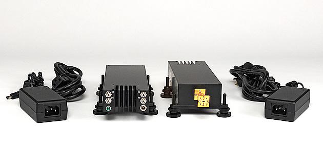
| Power Supply | AC Input | 100-240VAC, <3.5A, 50-60 Hz | U.S. or E.U. |
| DC Output | 9V / 4A | 2.1mm ID×5.5mm OD×9.5mm(f) | |
| Operating Temperature | Typical / Recommended | 25℃ / 20-30℃ | - |
| Typical Enclosure Dimensions | TxRx & TxRef Modules(in.) WR28 to WR19 | 9.5×3.0×1.5 | - |
| TxRx & TxRef Modules(in.) WR15 to WR2.2 | 8.5×3.0×1.5 | - | |
| TxRx & TxRef Modules(in.) WR28 to WR19, -Atten Option | - | - | |
| TxRx & TxRef Modules(in.) WR28 to WR19, -Atten Option | 8.5×3.0×1.5 | - | |
| Rx Modules(in.) [New, Serial Number: VNAX 2400 and higher] | 4.75×3.0×1.5 | - | |
| Rx Modules(in.) [Old, Serial Number: VNAX 2399 and lower] | 3.75×3.0×1.5 | - | |
| Typical Weight | TxRx & TxRef Modules(lbs.) | 4 | - |
| Rx Modules(lbs.) | 2 | - | |
| VNA Extension Modules VNA Extension Module(WR0.65) Standard Size |
|||
|---|---|---|---|
| Description | Specification | Connector | |
| RF Input | Standard Frequency Input(Typical / Damage) | 10dBm ± 3dB / 16dBm <20GHz | 2.9mm(f) |
| Standard Frequency Input(Typical / Damage) with -5m option | 2dBm ± 3dB / 8dBm <20GHz | 2.9mm(f) | |
| High Frequency Input(Typical / Damage) | 0dBm ± 3dB / 6dBm <45GHz | 2.9mm(f) | |
| LO Input | Typical / Damage(Default) | 10dBm ± 3dB / 16dBm <20GHz | 2.9mm(f) |
| Typical / Damage, -5M Option | 2dBm ± 3dB / 8dBm <20GHz | 2.9mm(f) | |
| IF Outputs(Reference and Measurement) | Maximum, Direct Connection(279MHz) | -9dBm | 2.9mm(f) |
| Maximum, Controller(7.6MHz) | -21dBm | 2.9mm(f) | |
| Test Port | VDI Precision Flange | フランジ図を参照 | UG-387/UM |
| Power Supply | AC Input | 100-240VAC, <3.5A, 50-60 Hz | U.S. or E.U. |
| DC Output | VDI-175のデータシートを参照 | ||
| Operating Temperature | Typical / Recommended | 25°C / 20-30°C | - |
| Typical Enclosure Dimensions | TxRx & TxRef Modules(in.) | 11×5×3 | - |
| Rx Modules(in.) | 8×5×3 | - | |
| Typical Weight | TxRx & TxRef Modules(lbs.) | 9 | - |
| Rx Modules(lbs.) | 4 | - | |
製品ラインナップ
Vector Network Analyzer(VNA)Extenders - Summary of Specifications
| Model | Frequency Coverage (GHz) |
Dynamic Range (BW=10Hz,dB) |
Test Port Power (dBm, typical) |
Stability (typical) | Test Port Input Limit (estimate, dBm, damage) TxRx, TxRef |
Directivity (dB, typical) |
|---|---|---|---|---|---|---|
| WR28 | Standard:26-40 Extended:- |
Typical:120 Minumum:110 |
13 | Magnitude(±dB):0.15 Phase(±deg):2 |
33 | 30 |
| WR22 | Standard:33-50 Extended:- |
Typical:110 Minumum:100 |
13 | Magnitude(±dB):0.15 Phase(±deg):2 |
30 | 30 |
| WR19 | Standard:40-60 Extended:- |
Typical:120 Minumum:105 |
17 | Magnitude(±dB):0.15 Phase(±deg):2 |
31 | 30 |
| WR15 | Standard:50-75 Extended:47-77 |
Typical:120 Minumum:110 |
18 | Magnitude(±dB):0.1 Phase(±deg):1.5 |
30 | 30 |
| WR15 SE Option | Standard:50-75 Extended:47-77 |
Typical:120 Minumum:110 |
13 | Magnitude(±dB):0.1 Phase(±deg):1.5 |
30 | 30 |
| WR12 | Standard:60-90 Extended:55-95 |
Typical:120 Minumum:110 |
18 | Magnitude(±dB):0.1 Phase(±deg):1.5 |
30 | 30 |
| WR12 SE Option | Standard:60-90 Extended:55-90 |
Typical:120 Minumum:110 |
13 | Magnitude(±dB):0.1 Phase(±deg):1.5 |
30 | 30 |
| WR10 | Standard:75-110 Extended:67-115 |
Typical:120 Minumum:110 |
18 | Magnitude(±dB):0.1 Phase(±deg):1.5 |
30 | 30 |
| WR10 SE Option | Standard:75-110 Extended:67-110 |
Typical:120 Minumum:110 |
-4 | Magnitude(±dB):0.1 Phase(±deg):1.5 |
20 | 30 |
| WR8.0 | Standard:90-140 Extended:- |
Typical:120 Minumum:110 |
16 | Magnitude(±dB):0.15 Phase(±deg):2 |
30 | 30 |
| WR6.5 | Standard:110-170 Extended:- |
Typical:120 Minumum:110 |
13 | Magnitude(±dB):0.25 Phase(±deg):4 |
30 | 30 |
| WR5.1 | Standard:140-220 Extended:- |
Typical:120 Minumum:110 |
6 | Magnitude(±dB):0.25 Phase(±deg):4 |
30 | 30 |
| WR5.1 EB Option | Standard:140-220 Extended:130-220 |
Typical:120 Minumum:110 |
6 | Magnitude(±dB):0.25 Phase(±deg):4 |
30 | 30 |
| WR4.3 | Standard:170-260 Extended:- |
Typical:115 Minumum:110 |
4 | Magnitude(±dB):0.3 Phase(±deg):4 |
28 | 30 |
| WR3.4 | Standard:220-330 Extended:- |
Typical:115 Minumum:105 |
1 | Magnitude(±dB):0.3 Phase(±deg):6 |
26 | 30 |
| WM-710 (WR2.8) |
Standard:260-400 Extended:- |
Typical:110 Minumum:100 |
-1 | Magnitude(±dB):0.5 Phase(±deg):6 |
23 | 30 |
| WM-570 (WR2.2) |
Standard:330-500 Extended:325-500 |
Typical:110 Minumum:100 |
-3 | Magnitude(±dB):0.5 Phase(±deg):6 |
10 | 30 |
| WM-380 (WR1.5)Mini |
Standard:500-750 Extended:- |
Typical:110* Minumum:95* |
-12 | Magnitude(±dB):0.4 Phase(±deg):4 |
7 | 30 |
| WM-250 (WR1.0)Mini |
Standard:750-1100 Extended:- |
Typical:95* Minumum:75* |
-23 | Magnitude(±dB):0.5 Phase(±deg):6 |
-3 | 30 |
| WM-164 (WR0.65**) |
Standard:1100-1500 Extended:- |
Typical:60* Minumum:40* |
-45 | Magnitude(±dB):1 Phase(±deg):20 |
-3 | 30 |
PXI VNAX
| Model | Frequency Band (GHz) | Test Port Power (dBm typical) |
P50xxA/B Streamline M980xA PXI VNA Dynamic Range (BW=10Hz,dB) |
P93xxA/B Streamline M937xA PXI VNA Dynamic Range (BW=10Hz,dB) |
|---|---|---|---|---|
| WR15VNATxRxM* | Standard:50-75 Extended:47-77 |
18 | Typical:110 Minimum:100 |
Typical:105 Minimum:95 |
| WR15VNATxRxM-SE* | Standard:50-75 Extended:47-77 |
13 | Typical:110 Minimum:100 |
Typical:105 Minimum:95 |
| WR15VNATxRxM-P | Standard:50-75 Extended:- |
13 | Typical:105 Minimum:95 |
Typical:105 Minimum:95 |
| WR12VNATxRxM* | Standard:60-90 Extended:55-95 |
18 | Typical:110 Minimum:100 |
Typical:105 Minimum:95 |
| WR12VNATxRxM-SE* | Standard:60-90 Extended:55-90 |
13 | Typical:110 Minimum:100 |
Typical:105 Minimum:95 |
| WR12VNATxRxM-P | Standard:60-90 Extended:- |
13 | Typical:105 Minimum:95 |
Typical:105 Minimum:95 |
| WR10VNATxRxM* | Standard:75-110 Extended:67-115 |
18 | Typical:110 Minimum:100 |
Typical:105 Minimum:95 |
| WR10VNATxRxM-SE* | Standard:75-110 Extended:67-110 |
-1 | Typical:110 Minimum:100 |
Typical:105 Minimum:95 |
| WR10VNATxRxM-P | Standard:75-110 Extended:- |
16 | Typical:105 Minimum:95 |
Typical:105 Minimum:95 |
| WR10VNATxRxM-P-SE | Standard:75-110 Extended:- |
-1 | Typical:105 Minimum:95 |
Typical:105 Minimum:95 |
| WR8.0VNATxRxM* | Standard:90-140 Extended:- |
16 | Typical:110 Minimum:100 |
Typical:95 Minimum:85 |
| WR6.5VNATxRxM* | Standard:110-170 Extended:- |
13 | Typical:110 Minimum:100 |
Typical:- Minimum:- |
| WR5.1VNATxRxM* | Standard:140-220 Extended:- |
6 | Typical:110 Minimum:100 |
Typical:N/A Minimum:N/A |
| WR4.3VNATxRxM* | Standard:170-260 Extended:- |
4 | Typical:110 Minimum:100 |
Typical:N/A Minimum:N/A |
| WR3.4VNATxRxM* | Standard:220-330 Extended:- |
1 | Typical:110 Minimum:100 |
Typical:N/A Minimum:N/A |
- 製品紹介ビデオ
-
IMS 2020 - VNAX Improvements
VDI社のVNA周波数エクステンダー(1.1THz対応)デモ