


ブロードバンド/ハイパワーマルチプライヤー(WR Series / D Series)
- カテゴリー
-
- RF、ミリ波、テラヘルツ
- マルチプライヤー
- 導波管マルチプライヤー
- ブロードバンド/ハイパワーマルチプライヤー(WR Series / D Series)
Virginia Diodes Inc.
概要
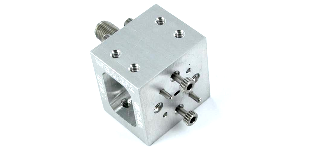
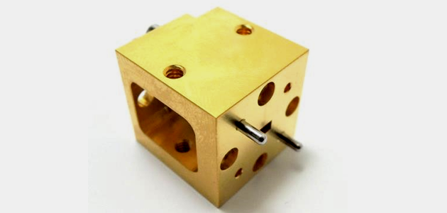
Virginia Diodes (VDI)社はプレーナGaAsショットキーダイオード技術に基づいた幅広いミリ波バリスタモードのパッシブ周波数マルチプライヤーを提供します。 周波数ダブラーおよびトリプラーはマイクロ波およびミリ波ソースの周波数カバレッジを拡張するために使用されます。
ブロードバンドマルチプライヤー
ブロードバンドダブラーおよびトリプラーは導波管の帯域全体にわたって高効率です。
広帯域ダブラー(2逓倍):WR-15(50-75 GHz)からWR-1.9(400-600 GHz)まで
広帯域トリプラー(3逓倍):WR-15(50-75 GHz)からWR-0.34(2200-3300 GHz)まで
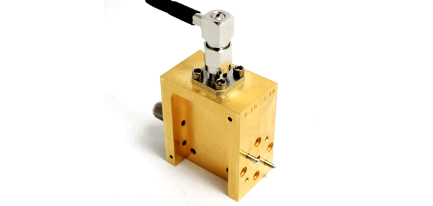
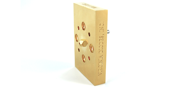
ハイパワーマルチプライヤー
VDIハイパワーダブラーは狭帯域(5〜10%のフラクショナル3 dB帯域幅)で高効率(最大40%)を提供します。
50 GHzから500 GHzまでの高出力ダブラーを提供します。 高出力ダブラーは特定のアプリケーション用に最適化できます。
その他の周波数
特定のアプリケーション用に最適化された代替周波数マルチプライヤーはご要望に応じて入手可能です。 詳細についてはお問い合わせください。
ダウンロード
ブロードバンド/Low パワー
WRシリーズ
| Frequency (GHz) | WR | Wide-Band Doublers (x2) | Wide-Band Triplers (x3) |
|---|---|---|---|
| 50-75 | WR-15 | WR15x2 | WR15x3 |
| 60-90 | WR-12 | WR12x2 | WR12x3 |
| 75-110 | WR-10 | WR10x2 | WR10x3 |
| 82-125 | WR-9.0 | WR9.0x3 | |
| 90-140 | WR-8 | WR8.0x2 | WR8.0x3 |
| 110-170 | WR-6.5 | WR6.5x2 | WR6.5x3 |
| 140-220 | WR-5.1 | WR5.1x2 | WR5.1x3 |
| 170-260 | WR-4.3 | WR4.3x2 | WR4.3x3 |
| 220-330 | WR-3.4 | WR3.4x2 | WR3.4x3 |
| 260-400 | WR-2.8 | WR2.8x2 | WR2.8x3 |
| 330-500 | WR-2.2 | WR2.2x2 | WR2.2x3 |
| 400-600 | WR-1.9 | WR1.9x2 | WR1.9x3 |
| 500-750 | WR-1.5 | WR1.5x3 | |
| 600-900 | WR-1.2 | WR1.2x3 | |
| 750-1100 | WR-1.0 | WR1.0x3 | |
| 1100-1700 | WR-0.65 | WR0.65x3 | |
| 1400-2200 | WR-0.51 | WR0.51x3 |
ナローバンド/High パワー
Dシリーズ
Specifications for Varactor Doublers*
| VDI Part # | RF Output Frequency (GHz)† |
Peak Efficiency (%)†† |
Typical 3dB Bandwidth (%)† |
RF Input Power Range (mW)†† |
Output Flange | Input Flange |
|---|---|---|---|---|---|---|
| D48 | 42 - 52 | 33 | 14 | 300 - 2250 | WR-19 UG-383/U | 2.9mm(f) |
| D52-W | 48 - 57 | 25 | 14 | 300 - 1950 | WR-19 UG-383/U | 2.9mm(f) |
| D52-N | 48 - 58 | 32 | 8 | 300 - 1950 | WR-19 UG-383/U | 2.9mm(f) |
| D58 | 48 - 65 | 32 | 14 | 450 - 1800 | WR-15 UG-385/U | 2.9mm(f) |
| D62 | 51 - 67 | 33 | 14 | 400 - 1800 | WR-15 UG-385/U | 2.9mm(f) |
| D72 | 64 - 79 | 28 - 30 | 14 | 400 - 1500 | WR-12 UG-387/U | 2.9mm(f) |
| D84 | 73 - 90 | 28 - 30 | 14 | 250 - 1000 | WR-10 UG-387/U-M | WR-22 UG-383/U |
| D90 | 86 - 96 | 30 | 10 | 200 - 900 | WR-10 UG-387/U-M | WR-19 UG-383/U |
| D102 | 92 - 109 | 27 | 14 | 200 - 700 | WR-10 UG-387/U-M | WR-19 UG-383/U |
| D108 | 92 - 124 | 30 | 10 | 250 - 1000 | WR-8.0 UG-387/U-M | WR-15 UG-385/U |
| D110 | 104 - 118 | 25 - 30 | 8 | 200 - 900 | WR-8.0 UG-387/U-M | WR-15 UG-385/U |
| D123 | 110 - 132 | 24 - 28 | 8 | 150 - 700 | WR-6.5 UG-387/U-M | WR-15 UG-385/U |
| D153 | 135 - 157 | 24 - 28 | 8 | 150 - 650 | WR-6.5 UG-387/U-M | WR-12 UG-387/U |
| D175 | 157 - 192 | 25 - 30 | 8 | 120 - 550 | WR-5.1 UG-387/U-M | WR-10 UG-387/U-M |
| D210 | 195 - 228 | 25 | 8 | 100 - 500 | WR-4.3 UG-387/U-M | WR-8.0 UG-387/U-M |
| D252 | 225 - 278 | 20 - 25 | 7 | 100 - 450 | WR-3.4 UG-387/U-M | WR-6.5 UG-387/U-M |
| D315 | 280 - 338 | 18 - 23 | 6.5 | 120 - 220 | WR-2.8 UG-387/U-M | WR-5.1 UG-387/U-M |
| D330 | 280 - 340 | 20 - 25 | 10 | 20 - 190 | WR-2.8 UG-387/U-M | WR-5.1 UG-387/U-M |
| D370 | 330 - 420 | 18 | 6 | 15 - 110 | WR-2.2 UG-387/U-M | WR-4.3 UG-387/U-M |
| D450 | 400 - 470 | 13 | 6 | 30 - 120 | WR-2.2 UG-387/U-M | WR-4.3 UG-387/U-M |
| D530 | 440 - 590 | 9- 13 | 5 | 10 - 80 | WR-1.9 UG-387/U-M | WR-3.4 UG-387/U-M |
| D650 | 580 - 680 | 9 - 13 | 5 | 8 - 75 | WM-380 UG-387/U-M | WR-3.4 UG-387/U-M |
†The RF Output Frequency range indicates the range over which the multiplier can be tuned. The lower and upper limits indicate the minimum and maximum 3dB bandwidth limits of the multiplier respectively.
††The multiplier can be configured to operate at an RF input power level within the wide RF input power range specified above. However, the multiplier is expected to operate approximately ±1dB centered around the RF input power level specified, not exceeding the maximum or minimum RF input power range listed above. Different biases may be required to achieve optimal performance across the full input power range specified above. Efficiency and 3dB bandwidth may be reduced at low RF input power levels. RF Input Power Damage Limit is expected to be approximately +2dB above the specified RF input power level specified, not exceeding the maximum RF input power listed above. See individualized datasheet for damage limit.
*This table is not a comprehensive list of all the varactor multipliers VDI offers. VDI may offer a different multiplier that is better suited for your application.
Specifications for Varactor Triplers*
| VDI Part # | RF Output Frequency (GHz)† |
Peak Efficiency (%)†† |
Typical 3dB Bandwidth (%)† |
RF Input Power Range (mW)†† |
Output Flange | Input Flange |
|---|---|---|---|---|---|---|
| T93 | 89 - 97 | 17 - 20 | 5 | 35 - 185 | WR-10 UG-387/U-M | 2.9mm(f) |
| T108 | 103 - 110 | 12 - 15 | 5 | 35 - 185 | WR-8.0 UG-387/U-M | 2.9mm(f) |
| T220 | 208 - 225 | 10 - 13 | 5 | 50 - 150 | WR-4.0 UG-387/U-M | WR-12.8 UG-387/U-M |
| T228 | 223 - 233 | 10 - 12 | 5 | 75 - 170 | WR-4.3 UG-387/U-M | WR-12.2 UG-387/U-M |
| T282 | 276 - 290 | 8 - 10 | 4 | 75 - 140 | WR-3.4 UG-387/U-M | WR-10 UG-387/U-M |
| T321 | 305 - 335 | 7 - 9 | 4 | 20 - 55 | WR-2.8 UG-387/U-M | WR-8.0 UG-387/U-M |
| T438 | 432 - 444 | 8 - 9 | 4 | 15 - 55 | WR-2.0 UG-387/U-M | WR-6.5 UG-387/U-M |
†The RF Output Frequency range indicates the range over which the multiplier can be tuned. The lower and upper limits indicate the minimum and maximum 3dB bandwidth limits of the multiplier respectively.
††The multiplier can be configured to operate at an RF input power level within the wide RF input power range specified above. However, the multiplier is expected to operate approximately ±1dB centered around the RF input power level specified, not exceeding the maximum or minimum RF input power range listed above. Different biases may be required to achieve optimal performance across the full input power range specified above. Efficiency and 3dB bandwidth may be reduced at low RF input power levels. RF Input Power Damage Limit is expected to be approximately +2dB above the specified RF input power level specified, not exceeding the maximum RF input power listed above. See individualized datasheet for damage limit.
*This table is not a comprehensive list of all the varactor multipliers VDI offers. VDI may offer a different multiplier that is better suited for your application.