


Virginia Diodes Inc.
製品のお問い合わせ
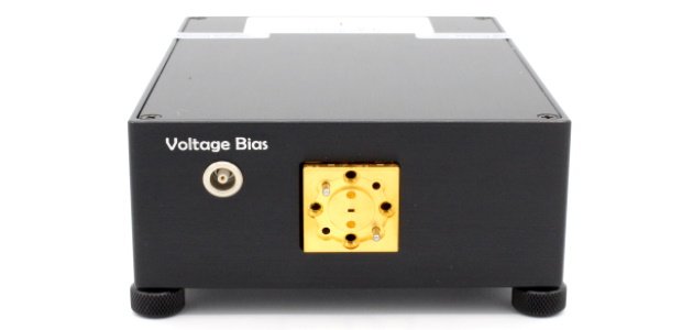
コンパクトコンバーター(CC)
- カテゴリー
-
- RF、ミリ波、テラヘルツ
- コンパクトコンバーター(CC)
Virginia Diodes Inc.
説明
Virginia Diodes Inc.(VDI) 社は周波数アップおよびダウンコンバージョン用のコンパクトコンバーター(CC)を提供しています。
これらのコンバーターは使いやすく、広帯域変調ミリ波信号の高性能アップおよびダウンコンバージョンに最適です。
CCは導波管の全帯域をカバーし、WR28(22.5~40GHz)~WR2.2(330~500GHz)まで利用可能です。
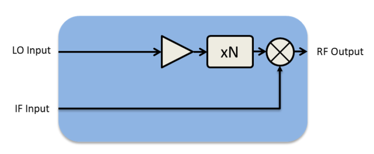
CCUの両側波帯の性質によりアップコンバージョンプロセス中に2つの側波帯(上側波帯と下側波帯)が生成されます。
特定のアプリケーションでは1つの側波帯を除去するためにフィルターが好ましい場合があります。
Virginia Diodes社のバンドパスフィルターの詳細については、こちらをクリックしてください。
アップコンバータからの送信信号出力を増幅する導波管増幅器も提供しています。Virginia Diodes社の増幅器の詳細については、こちらをクリックしてください。
コンパクトコンバータ構成
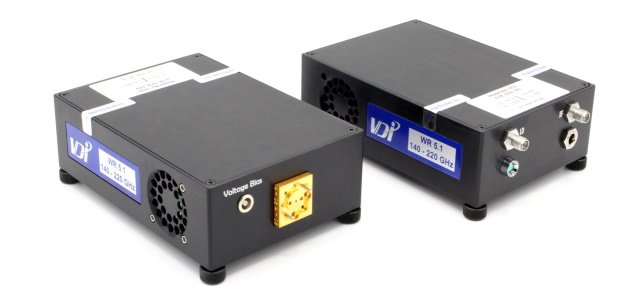
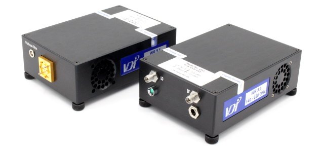
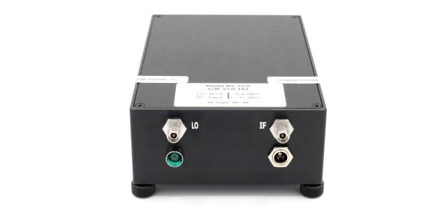
コンパクトアップコンバーター(CCU)
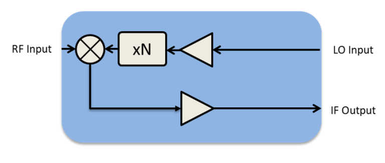
コンパクトダウンコンバーター(CCD)
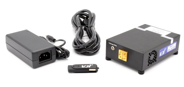
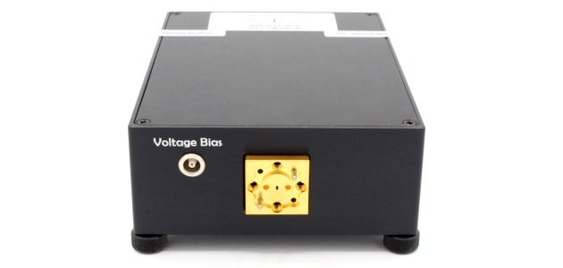
コンパクトコンバータ
コンパクトコンバータ(CC)の製品仕様
| RF Frequency (GHz) | Up Converter | Down Converter | LO Harmonic Factor | Intrinsic Mixer SSB Conversion Loss(dB, typ.)※1 | Maximum IF Frequency (GHz) |
|---|---|---|---|---|---|
| 22.5-40 | WR28CCU | WR28CCD | 1 | 9 | 8.5 |
| 40-60 | WR19CCU-B | WR19CCD-B | 2 | 10 | 9 |
| 50-75 | WR15CCU-B | WR15CCD-B | 2 | 10 | 14 |
| 50-75 | WR15CCU-B-M4 | WR15CCD-B-M4 | 4 | 10 | 14 |
| 60-90 | WR12CCU-B | WR12CCD-B | 2 | 10 | 12 |
| 60-90 | WR12CCU-B-M4 | WR12CCD-B-M4 | 4 | 10 | 12 |
| 75-110 | WR10CCU-B | WR10CCD-B | 4 | 10 | 15 |
| 90-140 | WR8.0CCU | WR8.0CCD | 4 | 10 | 15 |
| 110-170 | WR6.5CCU | WR6.5CCD | 6 | 10 | 17 |
| 110-170 | WR6.5CCU-M4 | WR6.5CCD-M4 | 4 | 10 | 17 |
| 110-170 | WR6.5CCU-M8 | WR6.5CCD-M8 | 8 | 10 | 17 |
| 110-170 | WR6.5CCU-M12 | WR6.5CCD-M12 | 12 | 10 | 17 |
| 140-220 | WR5.1CCU | WR5.1CCD | 6 | 11 | 22 |
| 140-220 | WR5.1CCU-M12 | WR5.1CCD-M12 | 12 | 11 | 22 |
| 170-260 | WR4.3CCU | WR4.3CCD | 6 | 11 | 26 |
| 170-260 | WR4.3CCU-M12 | WR4.3CCD-M12 | 12 | 11 | 26 |
| 220-330 | WR3.4CCU | WR3.4CCD | 6 | 12 | 50 |
| 220-330 | WR3.4CCU-M12 | WR3.4CCD-M12 | 12 | 12 | 40 |
| 260-400 | WR2.8CCU | WR2.8CCD | 12 | 13 | 40 |
| 330-500 | WR2.2CCU | WR2.2CCD | 12 | 14 | 40 |
※1:変換損失は、外部アンプを使用しない場合のミキサー固有の変換損失として定義されます。
一般注意事項
パフォーマンス仕様は、ミキサーに結合される最適なRFおよびLO電力を前提としています。
帯域端付近ではパフォーマンスが低下する場合があります。
変換損失は、指定された最大IF周波数まで、IFの関数として約1.5dB/10GHzの割合で増加します。
パフォーマンスは、帯域端でパフォーマンスが低下する標準的な値です。
- 製品紹介画像
-
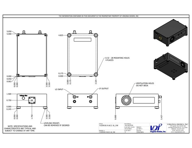
Current Drawings WR19
CCU/CCD With feet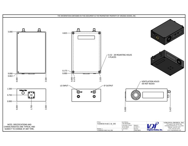
Current Drawings WR19
CCU/CCD Without Feet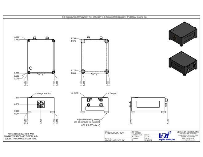
Current Drawings WR15 to WR10 (not -B Modules)
CCU/CCD With feet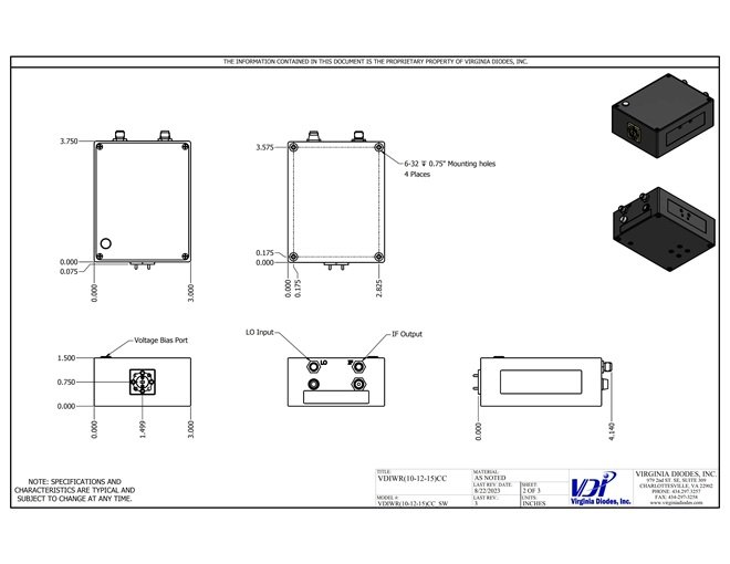
Current Drawings WR15 to WR10 (not -B Modules)
CCU/CCD Without Feet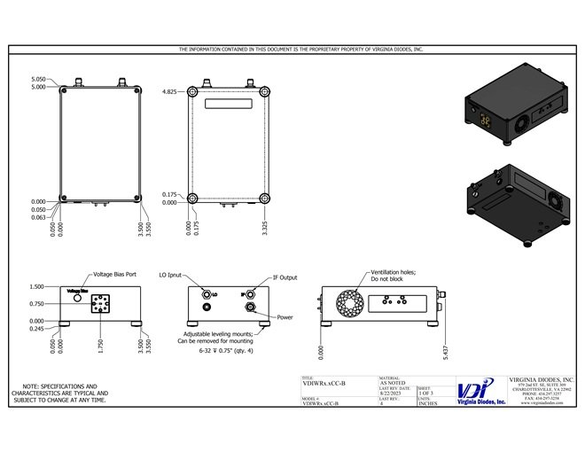
Current Drawings WR8.0 to WR2.2 and -B Modules for WR15 to WR10
CCU/CCD With feet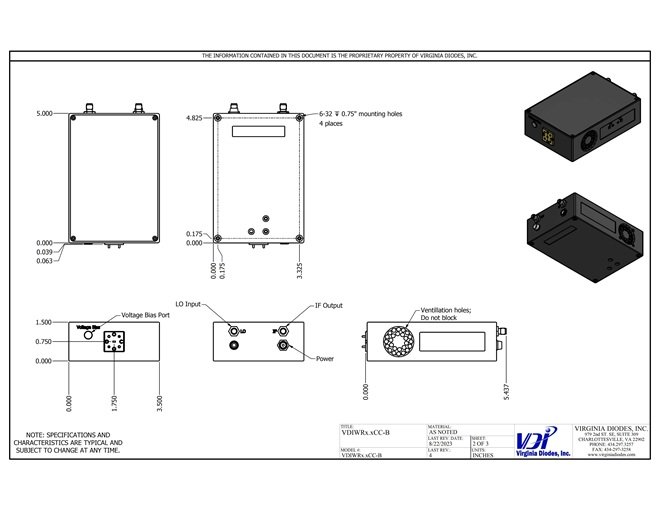
Current Drawings WR8.0 to WR2.2 and -B Modules for WR15 to WR10
CCU/CCD Without Feet